Why Treatment of The Water-Based Clay Slurries is Not Effective in Separation Attempts- The Microstructural Review
Marek S. Zbik1*
1 Faculty of Geology, University of Warsaw, ul. ?wirki i Wigury 93, 02-089 Warsaw, Poland.
*Corresponding Author: Marek S Zbik, Faculty of Geology, University of Warsaw, ul. ?wirki i Wigury 93, 02-089 Warsaw, Poland, Tel: 00-40-723621414; Fax: 00-40-253-210432; E-mail:marek.zbik@uw.edu.pl
Citation: Marek S. Zbik (2023) Why Treatment of The Water-Based Clay Slurries is Not Effective in Separation Attempts- The Microstructural Review. Arch Mol Med & Gen 3: 121.
Received: April 7, 2023; Accepted: April 17, 2023; Published: April 21, 2023.
Copyright: © 2023 Marek S. Zbik et al. This is an open-access article distributed under the terms of the Creative Commons Attribution License, which permits unrestricted use, distribution, and reproduction in any medium, provided the original author and source are credited.
Abstract
Smectites belongs to clay minerals were formed as result of the weathering of volcanic glass, lavas and igneous rocks like granites and basalts. They are useful for dam bed impregnation, to improve water retention properties and as drilling mud, to seal the cut, thus preventing fluid loss. Their peculiar microstructure building phenomenon causing the high-water retention makes these minerals popular as the stabilising additives in engine oils, cosmetics, pharmaceutical and chemical industries. This phenomenon so important in above mentioned activities is detrimental in dewatering clay rich sludge. Dewatering is a very important problem in mining waste utilization. All manipulations in designed clay-water pulp product crafted for particularly industry usage involved processes like aggregation, coagulation and flocculation using clarified reagents. To help understand micro structural behaviour of clay gelled suspension, the microstructure investigation was conducted using a variety of modern analytical techniques. All results advocate, the structure building phenomenon within entire suspension may be blame for poor settling and dewatering. All these may be result of high-water dielectric constant where polarised water molecules generate electric charge at the clay-water interphase. This charge leads to structure building phenomenon within the aqueous suspensions trapping water within structural voids. It becomes clear that further technologies have to eliminate using water in mineral processing and develop new approach involving close loop processing environment in fluids of the low dielectric constant.
Introduction
Among other high-aspect-ratio platy/flaky materials used across all applications, smectites are a popular ingredient of gels and form a base for a broad range of products in many industries, including pharmaceuticals, cosmetics, and petroleum. All important features which occurring as a result of the peculiar clay microstructure building phenomenon causing high water retention by these minerals. This prevents aggregates in clay-water suspension from settling under gravity force. This phenomenon so important in above mentioned activities cause difficulty in dewatering clay rich sludge. Particle space arrangement within the gel is an important factor that determines the physical properties of these minerals. These properties play a major role in the arrangement of technologies, such as the manipulation of colloidal stability, inks, and paints and coatings, as well as in engineering projects dealing with slurry dewatering, dams, footings, and slope stability. Even though many microstructural studies have been carried out around the world, the subject of fast settling slurries and water recovery is still poorly understood.Kaolinite, illite and expendable minerals like smectite and vermiculites, commonly classified as the sheet silicates (Grim, 1968) are the most common clay minerals, and are the primary cause of slow settling, slow filtration, and low dewatering because of superior water retention. These sheet silicates are platy in natural occurrence with high values of the ratio of platelet diameter to thickness, parameter known as the aspect ratio. For kaolinite, this aspect ratio is usually around 10 but can vary widely from very low values ~2 for stacks (or “books”) to more than 11 up to 36 for very thin platelets (Zbik & Smart, 1998; 1999). The aspect ratios for minerals from smectite group, such as montmorillonite, are generally much larger (e.g., 80-500). Hence, contrary to kaolinites, the area of the basal planes dominates in smectites over the area of edge sites. Because of this extremely high aspect ratio in smectites the function of charge dependency of the solution pH is negligible in comparison to kaolinites and illites (Kosmulski 2009, Alkan et al., 2005). Contemporary approaches to describing behaviour of dilute clay suspension are based on colloid stability (DLVO) theory developed independently by Derjaguin & Landau (1941) and Verwey & Overbeek (1948) This theory involves competition between electrostatic and van der Waals forces which generally decide whether particular colloid clay suspensions will be stabilised (in sol form) or coagulated (in gel form). Using pH variation, cation valency and salt concentration changes may collapse the electrical double layer which will lower the electrokinetic potential and allow van der Waals forces to bond particles that are close enough into larger aggregates which significantly increase settling rates.
The DLVO theory well describing colloidal systems behaviour is not strictly successful in application to the clay colloidal system. This may be happened because theory deals with most ideal colloids which colloidal particles of diameter below (0.5 µm) have spherical shape. However, the clay colloidal particles have high aspect ratio and particularly smectites aspect ratio may reach very high number up to 500. Such platelet shape particles may form aggregates and gel in countless combinations of individual particle orientation. Oriented in the specific way particles build a structure which has major impact on physical behaviour of the entirely system and its flocculation ability. This profound ability of structural behaviour, like building 3D cellular network was theoretised before and described from direct observation in (Zbik et al., 2008).
Figure1: Contemporary approaches to describing behaviour of dilute colloidal suspension are based on colloid stability (DLVO) theory.
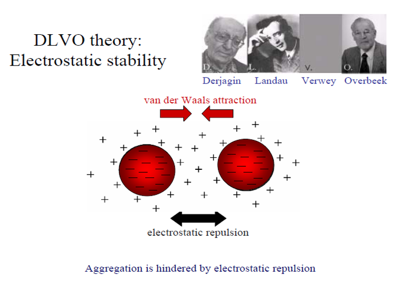
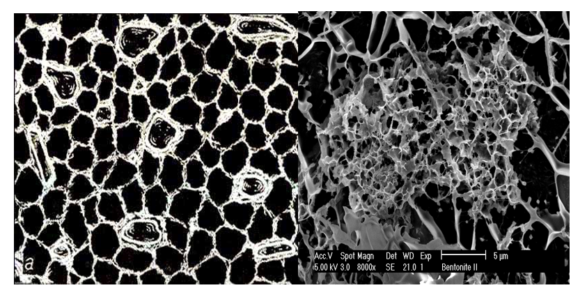
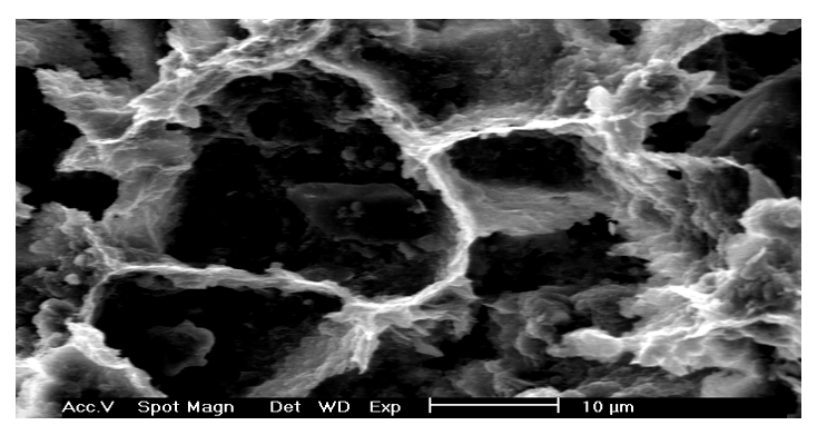
Figure 2: Example of cellular, the honeycomb microstructure within clay suspension in: 2A- theoretised from the fresh clay sediments obserwations in (Grabowska-Olszewska, 1984), 2B- Cryo-SEM observed in smectite suspension with non univorm density of coagulates, 2C- Cryo-SEM observed from smectite 20% kaolinite 80% suspension.
The first experimental confirmation of the clay gel structure was obtained with the advent of transmission electron microscopy (TEM) and scanning electron microscopy (SEM). Rosenquist (1959) published a micrograph confirming the existence of the “card house” structure. Bowles (1968) and O’Brien (1971) confirmed the presence of the honeycomb microstructure in wet clay sediments. Grabowska-Olszewska et al., (1984) using cryo-SEM investigations published a large amount of microstructural data from 86 studied samples of wet clay rocks combined with compositional and physical properties. Given the size of clay constituents, SEM was found to be the tool of choice used by scientists studying the microstructure of clays (Smart & Tovey, 1982).Sample preparation methods available for such investigations, like partial freeze drying, critical point-drying and cryo-fixation; have been found to introduce many artifacts especially when applied to the study of montmorillonite structure (O’Brien, 1970). These artifacts result as a consequence of the low thermal conductivity of water and ice, which only allows a slow rate of heat withdrawal from the specimen. Thus, the size of the gelled montmorillonite sample must be small enough to freeze quickly limiting the inevitable damage associated with the sampling process.
Primary dewatering processes include aggregate formation, bridging flocculation, settling rate and bed height (density) before compression. This can be achieved by physico-chemical processes like aggregation, coagulation and flocculation which were clarified in Osipov & Sokolov (2013). Aggregation is usually understood as a process of formation larger and stable structural elements by primary particles connecting in Face-to-Face phase contacts and becoming unstable. Coagulation is connected mostly with interaction between primary particles within dense suspensions (gels) resulting in Face to Edge (FE) and Edge to Edge (EE) coagulating type contacts. Flocculation also is seen as a process of building larger structural elements and some authors Van Olphen, (1963); Mitchell & Soga, (2005) relate this with coagulation. Others present flocculation as a separate type of coagulation to be achieved by flocculation using long chain polymers; however, this process is still not well understood. When solids concentration exceeds a certain value, the suspension gels and locks large and minute particles in a 3-D network leaving clear supernatant layer above the compacting gel (usually above 2 wt.%). Inside the gelled suspension free settling is not observed but more or less restricted hindered compaction takes place. Denser suspensions (4 wt. %) are very slow to compact and many high clays fraction content soil samples gelled and resist settlement. Kotlyar et al., (1998) and O’Brayen (1971) suggest but did not observe that particles in such gels are in constant contact with each other by creating a 3-D structure. Such a structure was reported in the first ever SEM observations of the clay particle in dilute suspensions O’Brayen (1971) where clay platelets were found to form networks with surrounding particles. The structure building phenomenon has been observed later in TXM (Zbik et al., 2008), in Cryo-SEM investigation (Zbik, 2006), and the nano-size particles (Kotlyar et al., 1996) were believed to be responsible. It has been found that a concentration of only 1 to 1.5 vol. % of nano particles is required to produce a space filling, gel network. Presence of the extremely small particles (nano-colloids) in a suspension was reported to enhance sample flocculation (Kotlyar et al. 1998). Within fraction containing particles of diameters, less than 200 nm, suspended in 0.1 M NaCl solution, gelatine was instantaneous. It was observed that larger particles were frequently immobilized within voluminous network of gelled suspensions or flocks. The gelled clay rich suspension has high water holding capacity. Water is encapsulated within inter-aggregate cellular micro voids. Such gelled suspension resists settling which was observed in many of tests curied. Because of the lack of free sedimentation and well-defined borders between flock aggregates, specific information such as in situ aggregate density distribution and flocks’ dimensions are very difficult or impossible to determine. To help understand micro structural behaviour of clay gelled suspensions and to find a way of characterizing the effects of certain treatments, the microstructure investigation was conducted using a Cryo-Transmission X-ray Microscope and resulting nanostructure was described by ?bik et al., (2008). The big advantage of the TXM tomography is the possibility of observing clay microstructure in a water environment, limited artefacts and without sample pre-treatment.
Materials and Methods
Commercially available Australian “Amcol” sodium smectite, clay mineral-rich bentonite, was chosen for this study. The product was sourced from Amcol Australia Pty Ltd., which owns and operates an Upper Jurassic bentonite mine at Miles in Queensland, approximately 375 km northwest of Brisbane (Exon, & Duff, 1968). Another smectite involved in this study was Na-bentonite sample from Wyoming, obtained from the Clay Minerals Society (Van Olphen, & Fripiat, 1979). The sudium bentonite is of the chemical formula Na0.33[Al1.67Mg0.33(O(OH))2(SiO2)4]. From non-treated bentonite, a 2.5 wt% suspension was prepared in deionised water (DI) as well as 0.1 M suspension in NaCl and CaCl2 salt and was sonicated for 1 min with power of 50 W. The pH was not controlled and was measured to be approximately 8 in a suspension. Electrokinetic potential (zeta potential or ζ) was measured in the clay samples using a Zetasizer (Nano-Series), manufactured by Malvern Ltd in the United Kingdom (UK). Samples of diluted suspension (∼0.2 wt%) were prepared from the clay fraction and inserted into the disposable measurement cell. This cell was placed in the instrument to conduct the measurements. Zeta potential in mV and electrical conductivity in mS/cm were measured in DI water and 0.1 M NaCl and CaCl2 salt suspensions, as described in Hunter (1981), Lyklema (2003), and Minor et al., (1997).
XRD patterns were recorded with a PAN analytical X-Pert Pro, which is a multi-purpose diffractometer that uses Fe-filtered Ca Kα radiation, auto-divergence slit, 2? anti-scatter slit, and fast X’-Celerator Si strip detectors. The diffraction patterns were rerecorded in steps of 0.016?2-theta with a 0.4 s counting time per step and logged to data files for analysis. A Nanoscope III AFM (Digital Instruments) was used in the force mode with scan head E. A standard ?uid cell and a scan rate of 0.1 and 1 Hz were used for all measurements. AFM cantilevers were triangular, tipples, silicon nitride. The spring constant was nominal 0.12N/m. Colloid probes were prepared by attaching a particle to the end of cantilever. Electron microscope investigations were conducted using JEOL-2100 TEM operating with a 200 kV accelerating potential. ASEM JEOL 6040 was used to investigate samples coated in platinum film with accelerating voltage of 15–20 kV. For three-dimensional (3D) imaging investigations were conducted on Zeiss Auriga 60 Cryo-SEM/FIB. and Cryo-TEM was used with an accelerating voltage of 300 kV. The aqueous suspension samples were vitrified at liquid nitrogen temperature by rapidly plunging the samples into an environment-stable camera (stable temperature and moisture content).
Results and Discussion
Smectite samples in Na and Ca solution shows very distinctive difference in surface charge as shown on electrokinetic potential (ζ – Zeta) values in Table 1.
Table 1: Electrokinetic potential and electrical conductivity of studied smectite sample in natural pH ∼ 8.
|
Medium |
Zeta potential in mV |
Electrical conductivity in mS/cm |
|
DI water |
- 61.4 |
0.00144 |
| 0.1 M NaCl |
- 39.6 |
13 |
| 0.1 M CaCl2 |
- 12.6 |
22.6 |
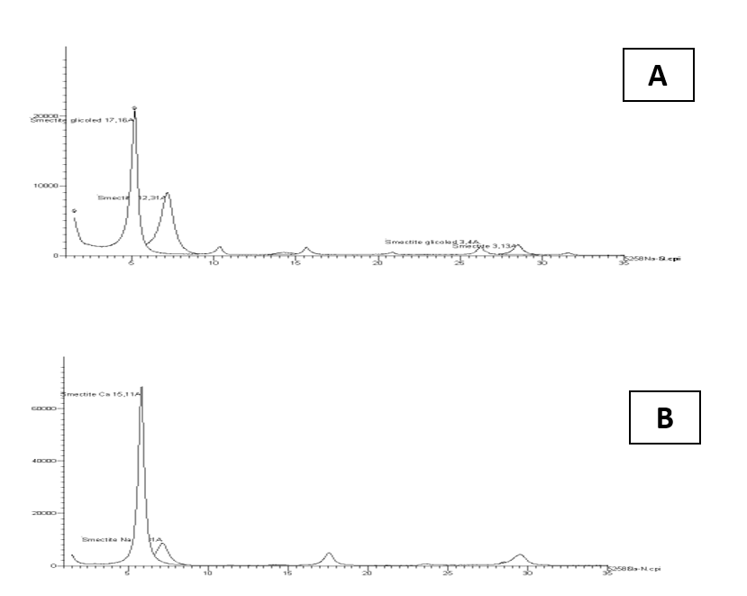
From Table. 1 can be learned that smectite platelets have significant charge regardless aqueous medium physic-chemical properties. This charge depends however on of water ionic strength as seen from electrical conductivity values. The largest negative charge value was measured for smectite particles within deionized water (DI). Charge was reduced significantly with increase of the solution ionic strength. This finding is consistent with DLVO predictions. In some cases, under influence of multivalent ions, like molecules Keggin Al+13 (Zbik et al, 2010) the Zeta charge can be reversed to positive. Thus, in any situation the smectite flakes experience strong electrical repulsion forces when approaching each other in an FF orientation. The high particle aspect ratio made the edge surface contribution towards the total value of the surface area insignificant, causing electrical potential spillage towards the edges, which also became unfavorable to forming face-to-edge contacts. However, the relatively small surface area of smectite edges may result in relatively low electro-static repulsion between particle edges in such an EE orientation. Therefore, the van der Waals attractive forces may prevail, and EE contacts between thin smectite flakes may become favorable in such a colloidal system. The XRD results display in Fig. 2 show almost pure smectite composition with small admixture of quartz. Sample treated in NaCl solution (Fig. 2A) displays major 001 peak at d-space 12,31Å and this peak after glicolation produce narrower and higher peak with shifts towards larger d- space 17,16 Å. Clay treated in CaCl2 solution produce strong and narrow peak with d- space 15,11 Å. In Na saturated smectite, the mine 001 peak may be mobile along the d- space length depends on the moisture content in contrast to Ca saturated smectite which mine peak is rather stable.
Figure 3: XRD pattern of studied clay fraction of smectite after and before glicolation shows larger ability to open internal structure in sodium ions saturated sample. 3A- sodium saturated, 3B- calcium saturated.
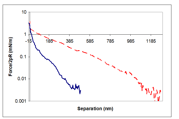
AFM investigation on the oriented clay layers on top of the silicon wafer was chosen because it is very hard to locate the individual clay platelet and position the colloidal probe directly over it. In part this is due to the low refractive index difference between different clay crystals and water leading to low optical contrast and visibility of the platelet under water, and in part it is due to the mechanical arrangement of the AFM. The thickness of the clay ?lm was not measured but samples were prepared as thin layer (on silicon wafer) as speci?ed in method above. In presented force–separation curves along-range repulsion has been recorded in DI water. This is the signature of double-layer repulsion. Its presence indicates that, the clay/water interface must be negatively charged. Direct measurements of forces acting between the studied Na and Ca-smectite and microscope cantilever were performed. Results plotted in figure (Fig. 4) above found(a) there is a long-range repulsion between these two surfaces; (b) the decay of the force is quasi-exponential; and (c) there is no adhesion between these surfaces. The long-range repulsive forces for Na- smectite have been detected from distances of over 1000 nm of the surface separation whereas for Ca- smectite the repulsive forces were detected from a distance ~400 nm. These numbers correspond to the cellular dimensions observed in TXM 3-D reconstruction as well as the 2-D TXM micrographs.
Figure 4: Force - separation curves for the interaction between smectite on silicon wafer on approach. The dashed line - Na+ exchangeable cations, solid line – Ca2+ exchangeable cations.
Microscope Morphology Studies
As reported in Zbik at al., (2008) and shown in 2-D, TXM micrographs (Fig. 5) reveal the gel structure in water. In the micrograph shown in Fig. 5A, elongated smectite sheets form a cellular network that is 0.6-1.5 µm in diameter (average 940 nm). In the 2-D TXM micrograph of the smectite gel (Fig. 5B), the cellular structure shows much smaller cells dimensions of 300-600 nm. The average distances measured between smectite sheets was around 450 nm. This is less than half of the cellular distance measured in Na- smectite. Smectite in a water suspension forms a gel where the individual thin stacked sheets are very ?exible and interact by a combination of edge attraction and basal plane repulsion. These properties can build an expanded and extremely voluminous cellular network composed of chain like sheet assemblies similar to those presented in the cryo-SEM micrograph (Figure 2B, & C). In such an extended cellular network smectite, ?exible sheets encapsulate water within cellular voids with dimensions of up to 0.5-2 µm. This ?ocked cellular structure can span the entire volume of the clay slurry. In such a case, the suspension is gelled; there is no free settling in the system, and further compacting may proceed slowly by structural rearrangement of the entire network. In a 3-D structure, smectite sheets are not oriented in any particular direction; therefore, their most probable orientation in the volume of suspension is random.
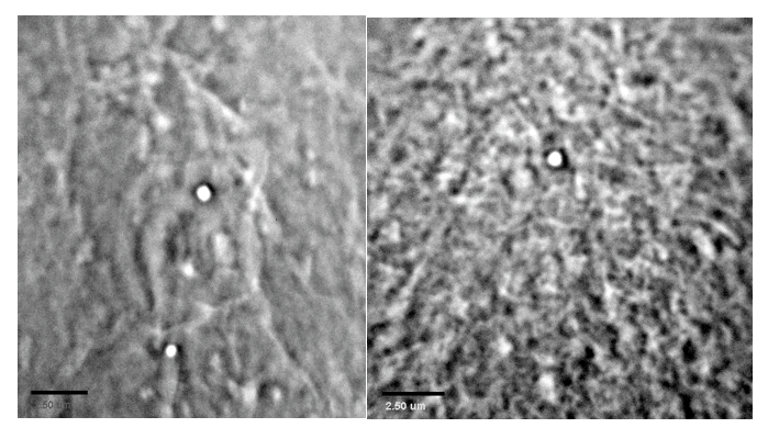
Figure 5: TXM micrographs show smectite suspension in A- 0.01 M NaCl, Large cellular structure of few micrometers can be seen with smaller structures inside these large cells. B- 0.01 M CaCl2, Cellular structure has much smaller and more uniform cells not larger than one micrometer in diameter.
Smectite samples were tested using SEM, TEM and Cryo-SEM. The SEM method is the most popular. The microscope is relatively easy to use and gives excellent micrographs. However, a sample should be carefully prepared for this test. The SEM microscope gives an image drafted from the reflected or scattered electrons. To remove the excess of the electric charge coming from the electron beam sample must covered with a thin layer of conductive material. Usually, it is coated ultrathin layer of carbon or alloy, for example, gold with palladium. Unwanted effect of this coating is hiding very small morphological details under. SEM is therefore very good method for minerals with not display very high degree of fragmentation. Practically, you can only study grains not smaller than one micron. The micrograph (Fig. 6A) shows an aggregate of several smectite grains build of individual clay particles curled into undistinguished shapeless grains. Layered sheets with dimensions of several microns are coupled to each other and as can be seen at this micrograph they are made of unknown number of smaller elements (particles). Due to the strong aggregation of these smaller particles within grains and sample blanketing with a layer of metal coating, there is not much more to say about the tested sample.
Samples of smectite which were tested using the TEM method shows much more details and can be studied under larger magnifications in comparison to SEM method. Translucent for electrons, the smectite aggregates displayed in the TEM micrograph (Fig. 6B) shows much better morphology details of its fundamental components. This micrograph shows an elastic smectite flake. It is heavily wrinkled, curled and bent which occurred as result of sample drying before putting it into the vacuum of the microscope column. The observed smectite sheet is relatively small because it is only about one micron in diameter. These sheets were result of disaggregation of larger curled aggregates like seen in SEM micrograph. On the TEM micrograph larger aggregates cannot be observed and only micron in size particles liberate from much complex aggregates can be studied. The observed smectite sheet appears to be a thin and undulating which tells about its soft flexibility. It is not a rigid particle. Similar flakes are visible on TXM micrographs (Fig. 5A). They build the cell walls of the suspension honeycomb microstructure. However, if you look closely at the SEM micrograph, you can see that this sheet is also made of even more fundamental flat leafs with nanometer of tens of nanometers. These leaves are arranged in parallel layered, book-like stacks and constitute the so-called book aggregates. Individual sheets of these aggregates can be liberated from these larger stacks, thus obtaining an extremely fine material called nano-clay. This finest ingredient can no longer be well traced in the routine TEM technique using the most common procedure. Special sample preparation and a properly tuned microscope can, however, deal with this problem. Samples of smectite suspension studied with Cryo-TEM technique show much more fine elements of the aggregate internal architecture.
Figure 6: Electronomicroscopy micrographs of smectite agregates. 6A- SEM micrographs show few aggregates of curled smectite sheets. 6B- TEM micrograph show translucent and wrinkled smectite sheet which is composed of much smaller fundamental particles (nao-clays) scale bar 500 nm.
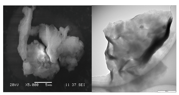
Figure 7: Cryo-TEM micrographs of smectite suspension (scale bar 100 nm). 7A- Larger micro-aggregate shows complex aggregate one micron in diameter consists of few much smaller curled micro-aggregates which constitute of even much smaller, curled and bent individual scale-like shits. 7B- Small micro-aggregate of three stacked smectite books shown different stages of individual sheet-scale liberation and bending. 7C- highly dispersed sheets of thin stacked smectite platelets.
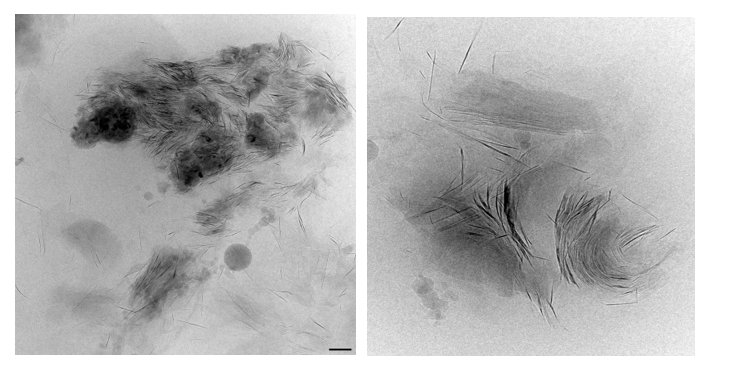
In the micrographs shown in (Fig. 7), smectite aggregates vitrified in aqueous suspension can be observed at very large magnification. It may tell that in spite effort of long sonication individual sheets were not fully liberated. Suspension sample still contains large amount of larger, micron in size aggregates (Fig. 7A) which constitute of stacked submicron-aggregates (Fig. 7B) containing not liberated individual scale-like smectite stacks constituented of scale-like sheets which were in different stadium of liberation and bending. In these micrographs, as well as in (Fig, 7C) individual, partly and fully liberated scale-like sheets can be displayed. In this sodium-based solution these platelets are far apart in FF orientation or in EE close coagulate type contact. These smectite individual sheets of 10 – 200 nm in diameter and one to few nm thick consist of singular and multilayered crystals of aspect ratio larger than 100. These liberated nano-clays when observed in three-dimensional micrographs (Fig.) show it microstructural connectivity which forms spanned network large, spaced aggregates or through entire suspension.
Figure 8: 3D anaglyphs showing the space arrangement of smectite particles in an aqueous environment (scale bar 100 mn), as observed in the Cryo-TEM. (8A)- in 0.1 M NaCl. (8B)- in 0.1 M CaCl2.
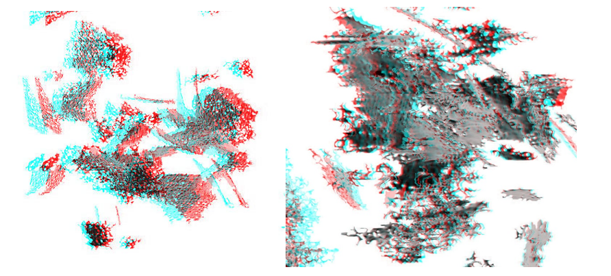
The three-dimensional aggregates were reconstructed from Cryo-TEM images taken from different angles and processed to short movies and 3D anaglyphs as shown in Fig. In micrograph at Fig. 8A highly spacious coagulates are visible and consist of liberated nanoscale smectite plates oriented exclusively in edge to edge (EE) and edge to face (EF) orientation. However, thanks to high electrokinetic potential in sodium diluted solution distances between particles are as large as their diameters. They produced a highly coagulated flock of very large voids between flocked particles. This flock may not be stable and its stability may depend of aqueous electrolyte chemistry. In Fig. 8B similar reconstruction of Cryo-TEM images taken from calcium based smectite suspension show much more compact coagulates in which many individual plates also in EE, EF and some in FF configuration. The only difference between those two systems is compactness of coagulates involved. Both are not stable and may change dependent of void water chemistry. Both are spacious, highly porous and contain voids which may retain substantial amounts of water. In an effort to obtain pure liberated sodium-based suspension, the sample was intensely sonicated and centrifuged three times on revolution 4000 per min. The aluminium chlorohydrate ten times diluted in water solution was titrated into smectite aqueous suspension in sol form, until it rapid transformed into gel. The electrokinetic potential was monitored by Zetasizer (nanoSeries) manufactured by Malvern Ltd. in United Kingdom. Zeiss Auriga 60 Cryo-SEM/FIB was used in studying vitrified gel sample accordingly to procedure in Zbik, at al., (2017). As the result described in (Zbik, et al., 2017), new globular flock morphology was observed where flexible smectite flakes were curled and build globular aggregates. These aggregates in many places were observed to assembly multilayer, micelle-like globular superstructure. Gel is prepared in reduced to zero electrokinetic potential. In such a system no repulsion shall exist between individual particles. Resulting highly viscous gel permanently retains all water and makes structure very stable for long time displaying semi-plastic behavior. Particles within the observed framework of hydrogel were contacting probably in the secondary energy minimum in comparison with highly charged particles gelled by contacting particles in primary energy minimum when platelets were electrically charged. In the recent study (Zbik & Williams, 2017) was applied different ways of treatment on kaolinite clay in effort to squeezing water from inside microstructure multiple treatment were deployed such as: changes of solution pH2, treated by microwave in DI water of varied pH values, treated by ultrasound in DI water, as well as in different pH, flocked by low anionic flocculent, flocked by high anionic flocculent, also after addition of 3 wt.% of smectite in DI water, and after addition of 3 wt.% smectite in DI water treated by ultrasound. In conclusion, none of undertaken methods was able to improve significantly dewatering the clay pulp. The rigid microstructure of clay skeleton retained water which was arrested within voids. Some new light on this subject in the author’s view may be encrypted in microstructural investigation of clay soils polluted by diesel fuel at places where such fuel depots were located. In an article (Trzcinski et al., 2015) authors described clay hydrophobised surface display much compacted aggregates with larger open interconnected void systems which is much easily drained from pore water.
Conclusions
Hindered Settling: When coagulated suspension aggregates are not uniformly spanning all volume but form separated clusters, they usually collapse towards the bottom of the vessel. In such case spaces between the clusters narrow, and finally the clusters became connected in a three-dimensional network forming highly voluminous sediment. In most studied problematic, not easy settled clay suspensions, particles are arranged in 3D network, which is spanned, and hindering effect generate forces preventing particles against settling. In this stage platelets are stacked into multilayer aggregates and build rigid skeleton of the cellular superstructure. This structure consists of cells a few µm in diameter filled with aqueous solution divided by walls built of multilayer stacks (aggregates) of clay platelets in FF orientation covered by nano in size and expandable platelets (because of electric charge differences). Voids inside such aggregates are hundreds and tens of nanometres in diameter and probably not readily penetrable to aqueous solutions. From all microscopy observations of the clay suspension in aqueous solution it is clear that particles in studied suspension were mostly in coagulated stage. Sodium saturated coagulated clays will produce much spacious skeleton of cellular microstructures in comparison to calcium saturated clays. However, in all circumstances, like shown in Fig. 8, similar highly porous microstructure was observed where particles contacting in EE and FE orientation. The only difference was fact that voids in sodium saturated clays were larger in comparison to calcium saturated. The only known to author FF clay platelets orientation was these described from compacted sediments (Grabowska-Olszewska, 1984). When Zeta potential approaching to the near zero value, suspension may gel which will lock particles into the secondary energy minimum. So, very stable gel may be produce as reported in (?bik, et al., 2017). Problematic clays have proved their ability to build 3D cellular network, caused by interaction of micro and nano-in size mineral platelets which skeleton may be electrically charged. Platelets carry negative charge on the flat surfaces and positive charge on edges. So, in the aqueous solution of low ionic strength, where particle flat surfaces are highly charged, suspension is in sole form and particles repels from each other. However, when charge diminishes because of increase ionic strength of a solution diversity of charged sides plays important role in particles orientation and building flocks and spanned network which retains all water within spacious structural voids. Such a network, because of hindered settling behaviour is most likely the major obstacle to successfully particle settling by flocculation. Any attempts to dewater such pulps have to destroy existent micro structural network and lower particle charge before designed flocculent addition.
Important role of nano-clays needs to be further study and shall be focus on nano in size colloidal particles role in coagulation. Extremely small size of these nano-clays sometime called as the “invisible clays” plays important role in flocculation. This may be because the electric charge diversification is high and complex across these particles and is not in well understood competition with van der Waals which factors sharpen clay microstructure within fluid suspension. High dielectric constant of water plays most important role in charge inducting at water-mineral interphase. So, it is important to understand that for some application in which certain electric charge and strong water retention phenomena will be beneficial for other application like dewatering, these properties are detrimental. In such applications in which fluids retention would be detrimental it may be recommender to use liquids of low dielectric constant as a medium for processing nanomaterials like clays and likewise. Influence of hydrocarbons on clays are not well known yet and other liquids like CO2 used for critical point drying also may be suitable in close loop processing for pharmaceutical or in space exploration applications.
References
- Alkan, M, Demirbas, O, Dogan, M (2005) Electrokinetic properties of kaolinite in mono- and multivalent electrolyte solution. Microporous and Mesoporous Materials 83: 51–59.
- Bowles, F A (1968) Science 159: 1236–1237.
- Chipera, SJ, Bish, DL (2001) Baseline studies of The Clay Minerals Society Source Clays: Powder X-ray diffraction analyses. Clays and Clay Minerals 49: 398-409.
- Derjaguin BV, Landau LD (1941) Theory of the stability of strongly charged lyophobicsols and of the adhesion of strongly charged particles in solutions of elec-trolytes, Acta Physicochim. URSS 14: 633–652.
- Exon NF, Duff PG (1968) Jurassic Bentonite from the Miles District, Department of National Development, Bureau of Mineral Resources Geology and Geophysics, Queensland.
- Grabowska-Olszewska B, Osipov V, Sokolov Vi (1984) Atlas of the Microstructure of Clay Soils; PWN: Warszawa.
- Grim, RE (1968) Clay Mineralogy. McGraw-Hill Book Company. New York 596.
- Hunter RJ (1981) Zeta Potential in Colloids Science. Academic Press. New York.
- Kosmulski M (2009) pH- dependent surface charging and points of zero charge. IV. Update and new approach. Journal of Colloid and Interface Science 337: 439-448.
- Kotlyar, LS Sparks, BD Shuttle R (1996) Effect of salt on the flocculation behaviour of nano particles in oil sand tailings. Clays Clay Minerals 44: 121-131.
- Kotlyar LS, Sparks BD, LePage Y, Woods JR (1998) Effect of particle size on the flocculation behaviour of ultra-fine clay in solutions. J.R. Clay Minerals 33: 103-107.
- Lyklema J (2003) Lyotropic sequences in colloid stability revisited. Colloid Surf. A; Phys. Eng. Asp. 222: 5-14.
- Minor M, van der Linde, AJ Leeuwem HP, Lyklema J, et al. (1997) Dynamic aspects of electrophoresis and electrophoresis a new fast method for measuring particle mobilities. J. Colloid Interface Sci 189: 370-375.
- Mitchell JK, Soga, K (2005) Fundaments of Soil Behavior. New York: John Willey and Sons 577.
- O’Braien, NR (1970) Freeze Drying Technique in the Study of the Fabric of Moist Clay Sediments. Journal of Electron Microscopy 19: 277.
- O’Brien NR (1971) Fabric of Kaolinite and illite Floccules. Clays Clay Miner. 19: 353–359.
- Rosenquist JTJ (1959) Soil Mech. Found. DiVi Proc. ASCE Sm 85: 31–53.
- Smart P, Tovey NK (1982) Electron Microscopy of Soils and Sediments: Techniques; Clarendon Press: Oxford, UK.
- Trzcinski JT, Williams DJ, ?bik MS (2015) Can hydrocarbon contamination influence clay soil grain size composition? Applied Clay Science. 109-110, 49-54.
- Van Olphen H (1963) An introduction to clay colloid chemistry. NY A Willey-Interscience Publ. 301.
- Van Olphen, H Fripiat J J (1979) Data Handbook for Clay Materials and Other Non-Metallic Minerals. Pergamon Press: Oxford, UK 183.
- Verwey EJ, Overbeek JTG (1948) Theory of Stability of Lyophobic Colloids, Else-vier, Amsterdam, Netherlands.
- Zbik M, Smart RStC (1999) Atomic force microscopy in estimation of aspect ratio of colloidal kaolinite. In: Kodama, H, Mermut, AR, Torrance, JK (Eds.) In: Clays for Our Future. Proceedings of the 11th International Clay Conference. ICC97 Ottawa, Canada, 361-366.
- Zbik M, Smart RStC (1998) Nanomorphology of Kaolinites: Comparative SEM and AFM Studies. Clays and Clay Minerals 46: 153-160.
- Zbik M (2006) Micro-Structural explanation for differences in gelation properties of kaolinites from Birdwood (S Australia) and Georgia (USA) Clay Science12: 31-36.
- Zbik MS, Martens W Frost, RL Song, YF Chen, et al. (2008) Transmission X-ray Microscopy (TXM) reveals nano-structure of smectite gel. Langmuir 24: 8954-8958.
- Zbik MS, Martens W, Frost RL, Song, et al. (2010) Smectite flocculation structure modified by Al-13 macromolecules; as revealed by the Transmission X-ray Microscopy (TXM), Journal of Colloid and Interface Science 345: 34–40.
- ?bik MS, Williams, DJ Trzci?ski JT (2017) Micelle-Like Microaggregate Morphology in Framework of Gelled Montmorillonite. J Membr Sci Technol 7:1
- ?bik MS, Williams DJ (2017) Influence of Physical Treatment on Kaolinite Floccule Microstructure. Arch Pet Environ Biotechnol 109: 1-10.